CYX19-IIC pressure sensor
2021年3月5日
CYB0505 digital display pressure switch
2021年8月17日.png")

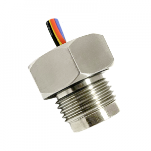
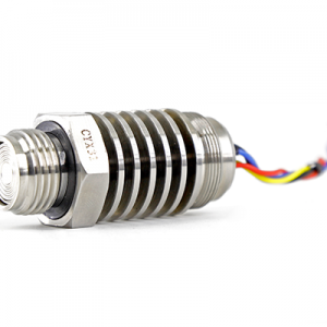
CYX19-007GfG pressure sensor
1 Overview
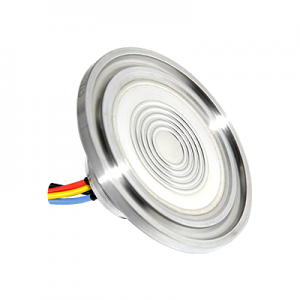
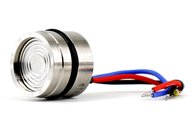
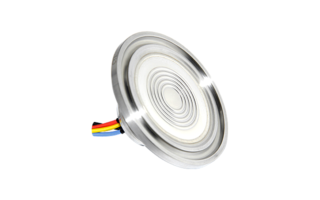
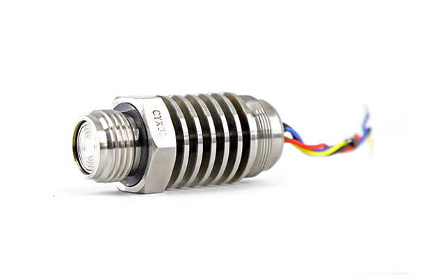
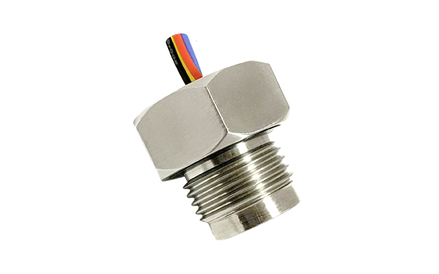
CYX19-007GfG is our latest minimum range oil-filled core pressure sensor. The shape, assembly size and sealing method of the product are the same as those of CYX19 series. It can be used for pressure, liquid level and flow detection within 10kPa.
2 Product features
- Measurement range 0kPa to 7kPa
- Table pressure G form
- Constant current/constant pressure power supply
- Isolated structure for a wide range of fluid media
- Φ19mm standard OEM pressure injection core body
- Full 316L stainless steel material
3 Main applications
- Industrial process control
- Liquid level measurement
- Gas and liquid pressure measurement
- Heating, ventilation and air conditioning
- Medical system
4 Technical specifications
(1 ) Electrical performance
Power supply: ≤ 3.0mA; DC ≤ 10V DC
Electrical connection: 0.2mm2 four-color 100mm silicone rubber flexible wire
Common mode voltage output: 50% of current-type input (typical), 40% of voltage-type input (typical)
Input impedance: 2.6kΩ~4.6kΩ
Output impedance: 4kΩ~6kΩ
Response time (10% to 90%): <1ms
Insulation resistance: 500MΩ/100V DC
Allowable overvoltage: 3 times full scale
(2) Structural performance
Diaphragm material: stainless steel 316L
Case material: stainless steel 316L
Pin lead: gold-plated Corvair
Seal ring: Buna-N, Viton (optional)
Net weight: about 23g
(3 ) Environmental conditions
Vibration: No change at 10gRMS, (20 to 2000) Hz
Constant acceleration: 100g, 11ms
Media compatibility: 316L and Buna-N (optional fluoroelastomer) for liquid or gas
(4) Baseline conditions
Medium temperature: (25±3)℃
Ambient temperature: (25±3)℃
Humidity:(50%±10%)RH
Ambient pressure:(86~106)kPa
Power source: (1.5±0.0015) mA DC
(5) Basic parameters
|
The number of arguments |
Typical value |
maximum |
Single bit |
|
Full-scale output |
65 |
80 |
mV |
|
Zero output |
±1 |
±2 |
mV |
|
Non-linear |
0.2 |
0.5 |
%FS |
|
Delay |
0.05 |
0.08 |
%FS |
|
Re-complex |
0.05 |
0.08 |
%FS |
|
Input/output impedance |
2.6 |
6.0 |
kO |
|
Zero temperature drift |
±0.5 |
±1.0 |
%FS,@25℃ |
|
Sensitivity temperature drift |
±0.5 |
±1.0 |
%FS, @25℃ |
|
Long-term stability |
0.1 |
0.2 |
%FS/year |
|
Excitation current |
1.5 (input voltage up to 10V) |
but |
|
|
Insulation resistance |
500(100VDC) |
M.I.A. |
|
|
Compensate for the temperature |
0~50 |
℃ |
|
|
Operating temperature |
-40~+125 |
℃ |
|
|
Store the temperature |
-40~+125 |
℃ |
|
|
Response time |
≤1 |
ms |
|
|
Housing and diaphragm material |
316L stainless steel |
|
|
|
O-seal |
Butyl rubber, fluoroelastomer, silicone rubber |
|
|
|
The measuring medium |
Fluids compatible with 316L, butyl rubber or fluoroelastomer or silicone rubber |
|
|
|
Lifespan (25 degrees C) |
>1×10⁸ Pressure Cycle (80%FS) |
times |
|
|
Fill the media |
Silicone oil |
|
|
|
Seals |
16×1.8mm (Ding Qing or Fluorinated Rubber Note 4) |
|
|
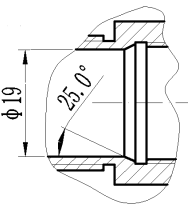
5 Selection structure
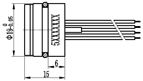
6 Schematics and wiring methods
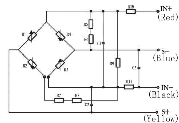
IN+ (Red line) – Power supply positive
IN-(Black line) – Power supply negative
S+(Yellow line)-Output positive
S-(Blue line)-Output negative
C1 to C3 capacitors for 103 porcelain media capacitors, battery-powered can be omitted according to user requirements
7 Application tips
- The sealing method of the pressure core body recommends the “suspended” sealing structure of the side wall O-ring to avoid front-end face pressure and prevent the stability of the pressure core body from being affected.
- Pay attention to protect the front diaphragm of the pressure core and the compensation circuit board at the back end so as not to affect the performance of the pressure core body or cause damage to the core body.
- The shell core cavity should be designed as shown in the cone angle, easy core assembly, to prevent right angle scratch seal.
- When assembling, pay attention to the core body size and the transmission housing inner shell tolerance match, it is recommended that the cavity according to the core body diameter of the 0.02 to 0.05 processing, in order to achieve the required air tightness.
- When assembling, put it vertically and press down evenly to prevent the shell from being crushed or the compensation sheet from being crushed.
- In the core compensation circuit, the positive power supply to ground and the positive and negative output to the ground respectively increased the capacitance of the porcelain media 0.01μF to improve the anti-jamming capacity of the core body. Users who require intermittent power supply for rapid response can request no capacitance in their order.
- Disable hands or hard objects from pressing metal diaphragms to avoid core damage due to chip deformation or perforation.
- When wiring, the core body pin should not be cut too short, the length is generally not less than 5mm, welding time is not greater than 5 seconds.
- The ventilation pipe at the rear of the G core body should be kept in contact with the atmosphere and water, water vapor or corrosive media should not be allowed into the reference cavity at the rear of the core.
- Avoid falling and bumping, etc. , will affect product stability.
- If there is a change in the pin lead, the physical carry label of the core body shall prevail.